
Мы предлагаем следующие способы доставки товара:
Самовывоз из пункта выдачи
Самостоятельное получение заказа в пункте выдачи. Дата и время получения заранее согласуется с менеджером магазина.
Отгрузка товара юридическим лицам осуществляется только при наличии печати или правильно оформленной и заполненной доверенности, наличии паспорта получателя.
Отгрузка физическим лицам, в случае оплаты заказа банковскими картами, возможна только при предъявлении паспорта плательщика.
Для получения заказа, оплаченного вышеуказанным способом, третьим лицом необходимо наличие нотариально заверенной доверенности.
Курьерская доставка по Москве
Доставка по адресу покупателя или до пункта приема транспортной компании в г. Москве. Дата и время доставки заранее согласуется с менеджером магазина.
Доставка транспортной компанией по России
Доставка транспортной компанией по России до пункта выдачи транспортной компании или до конечного адреса покупателя.
Мы предлагаем следующие способы оплаты товара:
Оплата за наличный расчет для физических и юридических лиц. После внесения денежных средств Покупатель подписывает товаросопроводительные документы и получает кассовый чек. Отгрузка товара юридическим лицам осуществляется только при наличии печати или правильно оформленной и заполненной доверенности, наличии паспорта получателя.
Мы работаем с физическими и юридическими лицами за безналичный расчёт со 100% предоплатой с оформлением всех предусмотренных законодательством документов. Счёт на оплату направляется Покупателю на электронную почту после запроса счета через форму на сайте либо по электронной почте. Цена на заказанный товар действительна в течение 2 дней с момента оформления Заказа.
Оплата Заказа электронными способами, в т.ч. банковскими картами. Оплата Заказа данным способом доступна запросом ссылки на оплату у нашего менеджера.
Мы предоставляем официальную гарантию на всю продукцию.
Сервис расширенной гарантии включает в себя:
- Приемку в сервисном центра для выполнения диагностики дефекта.
- Ремонт.
- Бесплатную доставку клиенту.
В рамках дополнительной программы оборудование Cisco Systems может быть поставлено с расширенной гарантией Cisco. Cрок расширенной гарантии Cisco – 12 месяцев с даты регистрации партнером продажи данного оборудования в базе данных компании Cisco Systems. По желанию клиента расширенная гарантия может быть продлена на следующие 12 месяцев по истечению первоначального срока или приобретена сразу на 24 или 36 месяцев.
Контакты гарантийного отдела:
Оставьте заявку в один клик и наш специалист свяжется с вами в кратчайшие сроки:
- Окажет профессиональную консультацию.
- Сообщит цену.
- Сообщит информацию об актуальных акциях и скидках.
- Подскажет ближайшее к вам отделение с наличием нужной продукции.
- Согласует с вами возможное время доставки.
WIFI точка доступа Cisco AIR-SAP702I внутренего использования, с 2-мя встроеными антеннами 2.4 GHz/5 GHz, 1 x GE RJ-45, 802.11a/b/g/n, 2×2 MIMO
AIR-SAP702I-E-K9 — беспроводная точка доступа серии 700 Cisco ® Aironet. Данная точка доступа отлично подойдет для клиентов, которые хотят модернизировать беспроводную сеть и сделать ее пригодной для самых современных требований.
- MIMO-возможности
- High Density-совершенство
- Услуга Cisco Network Assistant
- Table of Contents
- Getting Started Guide
- About this Guide
- Introduction to the Access Point
- Safety Instructions
- Unpacking
- Configurations
- Antennas
- Regulatory Domains
- Access Point Ports and Connectors
- Configuring the Access Point
- The Controller Discovery Process
- Preparing the Access Point
- Installation Summary
- Performing a Pre-Installation Configuration
- Pre-Installation Configuration Setup
- Deploying the Access Point on the Wireless Network
- Troubleshooting
- Guidelines for Using Cisco Aironet Lightweight Access Points
- Checking the Access Point LED
- Troubleshooting the Access Point Join Process
MIMO-возможности
AIR-SAP702I-E-K9 обладает двойным радиомодулем и множеством выходов MIMO, обеспечивающими по крайней мере шесть каналов с пропускной способностью до 300 Мбит/с, что намного превышает скорость предыдущего стандарта беспроводных сетей 802.11a/g.
High Density-совершенство
AIR-SAP702I-E-K9 обеспечивает безопасное и надежное соединение, обладающее рядом следующих преимуществ:
Услуга Cisco Network Assistant
Для быстрой и легкой настройки AIR-SAP702I-E-K9 данная услуга обеспечивает централизованное представление сети с удобным графическим интерфейсом, который упрощает настройку, управление и устранение неполадок. Использование Cisco Network Assistant помогает легко обнаруживать и инициализировать сеть автономных точек доступа.
Вся информация на сайте ru-cisco.com носит исключительно справочный характер и не является публичной офертой. Производитель оборудования Cisco оставляет за собой право на внесение изменений в конструкцию, дизайн и комплектацию оборудования без предварительного уведомления. Уточняйте подробную информацию о товаре у наших специалистов.
Мы предлагаем следующие способы доставки товара:
Самовывоз из пункта выдачи
Самостоятельное получение заказа в пункте выдачи. Дата и время получения заранее согласуется с менеджером магазина.
Отгрузка товара юридическим лицам осуществляется только при наличии печати или правильно оформленной и заполненной доверенности, наличии паспорта получателя.
Отгрузка физическим лицам, в случае оплаты заказа банковскими картами, возможна только при предъявлении паспорта плательщика.
Для получения заказа, оплаченного вышеуказанным способом, третьим лицом необходимо наличие нотариально заверенной доверенности.
Курьерская доставка по Москве
Доставка по адресу покупателя или до пункта приема транспортной компании в г. Москве. Дата и время доставки заранее согласуется с менеджером магазина.
Доставка транспортной компанией по России
Доставка транспортной компанией по России до пункта выдачи транспортной компании или до конечного адреса покупателя.
Мы предлагаем следующие способы оплаты товара:
Оплата за наличный расчет для физических и юридических лиц. После внесения денежных средств Покупатель подписывает товаросопроводительные документы и получает кассовый чек. Отгрузка товара юридическим лицам осуществляется только при наличии печати или правильно оформленной и заполненной доверенности, наличии паспорта получателя.
Мы работаем с физическими и юридическими лицами за безналичный расчёт со 100% предоплатой с оформлением всех предусмотренных законодательством документов. Счёт на оплату направляется Покупателю на электронную почту после запроса счета через форму на сайте либо по электронной почте. Цена на заказанный товар действительна в течение 2 дней с момента оформления Заказа.
Оплата Заказа электронными способами, в т.ч. банковскими картами. Оплата Заказа данным способом доступна запросом ссылки на оплату у нашего менеджера.
Мы предоставляем официальную гарантию на всю продукцию.
Сервис расширенной гарантии включает в себя:
- Приемку в сервисном центра для выполнения диагностики дефекта.
- Ремонт.
- Бесплатную доставку клиенту.
В рамках дополнительной программы оборудование Cisco Systems может быть поставлено с расширенной гарантией Cisco. Cрок расширенной гарантии Cisco – 12 месяцев с даты регистрации партнером продажи данного оборудования в базе данных компании Cisco Systems. По желанию клиента расширенная гарантия может быть продлена на следующие 12 месяцев по истечению первоначального срока или приобретена сразу на 24 или 36 месяцев.
Контакты гарантийного отдела:
Оставьте заявку в один клик и наш специалист свяжется с вами в кратчайшие сроки:
- Окажет профессиональную консультацию.
- Сообщит цену.
- Сообщит информацию об актуальных акциях и скидках.
- Подскажет ближайшее к вам отделение с наличием нужной продукции.
- Согласует с вами возможное время доставки.
Точка доступа Cisco AIR-CAP2702I-R-K9
802.11ac CAP w/CleanAir, 3×4:3SS, Int Ant, R Reg Domain
Вся информация на сайте ru-cisco.com носит исключительно справочный характер и не является публичной офертой. Производитель оборудования Cisco оставляет за собой право на внесение изменений в конструкцию, дизайн и комплектацию оборудования без предварительного уведомления. Уточняйте подробную информацию о товаре у наших специалистов.
Мы предлагаем следующие способы доставки товара:
Самовывоз из пункта выдачи
Самостоятельное получение заказа в пункте выдачи. Дата и время получения заранее согласуется с менеджером магазина.
Отгрузка товара юридическим лицам осуществляется только при наличии печати или правильно оформленной и заполненной доверенности, наличии паспорта получателя.
Отгрузка физическим лицам, в случае оплаты заказа банковскими картами, возможна только при предъявлении паспорта плательщика.
Для получения заказа, оплаченного вышеуказанным способом, третьим лицом необходимо наличие нотариально заверенной доверенности.
Курьерская доставка по Москве
Доставка по адресу покупателя или до пункта приема транспортной компании в г. Москве. Дата и время доставки заранее согласуется с менеджером магазина.
Доставка транспортной компанией по России
Доставка транспортной компанией по России до пункта выдачи транспортной компании или до конечного адреса покупателя.
Мы предлагаем следующие способы оплаты товара:
Оплата за наличный расчет для физических и юридических лиц. После внесения денежных средств Покупатель подписывает товаросопроводительные документы и получает кассовый чек. Отгрузка товара юридическим лицам осуществляется только при наличии печати или правильно оформленной и заполненной доверенности, наличии паспорта получателя.
Мы работаем с физическими и юридическими лицами за безналичный расчёт со 100% предоплатой с оформлением всех предусмотренных законодательством документов. Счёт на оплату направляется Покупателю на электронную почту после запроса счета через форму на сайте либо по электронной почте. Цена на заказанный товар действительна в течение 2 дней с момента оформления Заказа.
Оплата Заказа электронными способами, в т.ч. банковскими картами. Оплата Заказа данным способом доступна запросом ссылки на оплату у нашего менеджера.
Мы предоставляем официальную гарантию на всю продукцию.
Сервис расширенной гарантии включает в себя:
- Приемку в сервисном центра для выполнения диагностики дефекта.
- Ремонт.
- Бесплатную доставку клиенту.
В рамках дополнительной программы оборудование Cisco Systems может быть поставлено с расширенной гарантией Cisco. Cрок расширенной гарантии Cisco – 12 месяцев с даты регистрации партнером продажи данного оборудования в базе данных компании Cisco Systems. По желанию клиента расширенная гарантия может быть продлена на следующие 12 месяцев по истечению первоначального срока или приобретена сразу на 24 или 36 месяцев.
Контакты гарантийного отдела:
Оставьте заявку в один клик и наш специалист свяжется с вами в кратчайшие сроки:
- Окажет профессиональную консультацию.
- Сообщит цену.
- Сообщит информацию об актуальных акциях и скидках.
- Подскажет ближайшее к вам отделение с наличием нужной продукции.
- Согласует с вами возможное время доставки.

If you operate a small or medium-sized enterprise network, deploy the Cisco Aironet 1700 Series Access Point for the latest 802.11ac Wi-Fi technology at an attractive price. The 1700 Series meets the growing requirements of wireless networks by delivering better performance than 802.11n and providing key RF management features for improved wireless experiences.
The 1700 Series supports 802.11ac Wave 1 standard capabilities. That includes a theoretical connection rate of up to 867 Mbps.
The added throughput lets you stay ahead of growing bandwidth requirements as:
More wireless clients associate with the network
Mobile workers increasingly use multiple Wi-Fi devices
Features and Benefits
Building on the Cisco Aironet heritage of RF excellence, the 1700 Series access points run on a purpose-built, innovative chipset with a best-in-class RF architecture. The 1700 Series is a component of Cisco’s flagship, 802.11ac-enabled Aironet access points that deliver robust mobility experiences.
Table 1. Primary Capabilities and How You Benefit
To place an order, visit the Cisco Ordering Home Page. To download software, visit the Cisco Platform Suite.
Table 2. Ordering Information
Limited Lifetime Hardware Warranty
Cisco Wireless LAN Services
Flexible payment solutions to help you achieve your objectives.
Table of Contents
Cisco Aironet 1700 Series Access Points
About this Guide
Introduction to the Access Point
Access Point Ports and Connectors
Configuring the Access Point
The Controller Discovery Process
Preparing the Access Point
Performing a Pre-Installation Configuration
Pre-Installation Configuration Setup
Mounting the Access Point
Deploying the Access Point on the Wireless Network
Guidelines for Using Cisco Aironet Lightweight Access Points
Using DHCP Option 43
Checking the Access Point LED
Troubleshooting the Access Point Join Process
Declarations of Conformity and Regulatory Information
Manufacturers Federal Communication Commission Declaration of Conformity Statement
VCCI Statement for Japan
Guidelines for Operating Cisco Aironet Access Points in Japan
Statement 371—Power Cable and AC Adapter
Canadian Compliance Statement
European Community, Switzerland, Norway, Iceland, and Liechtenstein
Declaration of Conformity with regard to the R&TTE Directive 1999/5/EC & Medical Directive 93/42/EEC
Declaration of Conformity for RF Exposure
Generic Discussion on RF Exposure
This Device Meets International Guidelines for Exposure to Radio Waves
This Device Meets FCC Guidelines for Exposure to Radio Waves
This Device Meets the Industry Canada Guidelines for Exposure to Radio Waves
Cet appareil est conforme aux directives internationales en matière dqexposition aux fréquences radioélectriques
Additional Information on RF Exposure
Operation of Cisco Aironet Access Points in Brazil
Declaration of Conformity Statements
Configuring DHCP Option 43 and DHCP Option 60
Access Point Specifications
Getting Started Guide
About this Guide
This Guide provides instructions on how to install and configure your Cisco Aironet 1700 Series Access Point. This guide also provides mounting instructions and limited troubleshooting procedures.
The 1700 Series Access Point is referred to as the access point in this document.
Introduction to the Access Point
The 1700 series supports high-performing Spectrum Intelligence which sustains two spatial stream rates over a deployable distance with high reliability when serving clients. The 1700 series provides high reliability and overall wireless performance.
The 1700 series offers dual-band radios (2.4 GHz and 5 GHz) with integrated antennas. The access points support full interoperability with leading 802.11ac clients, and support a mixed deployment with other access points and controllers.
The 1700 series access point is available in both controller-based (Unified) and standalone (Autonomous) configurations, and supports:
- Simultaneous dual-band (2.4-GHz and 5-GHz) radios
- Integrated antennas (AIR-CAP1702I-x-K9)

Note The ‘x’ in the model numbers represents the regulatory domain. Refer to “Regulatory Domains” section for a list of supported regulatory domains.
The features of the 1700 series are:
- Processing sub-systems (including CPUs and memory) and radio hardware which supports:
– Network management
– CleanAir—Automatic detection, classification, location and mitigation of RF interference, with limited number of IDRs (Interference Device Reports) generated.
– Radio Resource Management (RRM)
– Rogue detection
– Management Frame Protection (MFP)
– Throughput, forwarding, and filtering performance scaled to meet 2 spatial streams, 1.3-Gbps data-rates
- 64 MB flash size
- 802.3af/802.3at compatible via CDP (Cisco Discovery Protocol) or LLDP (Link Layer Discovery Protocol)
- 2.4 GHz and 5 GHz 802.11n radios with the following features:
– 3TX x 3RX for 2.4 GHz and 5 GHz
– 2-spatial streams
– Spectrum intelligence
– DPD (Digital Pre-Distortion) technology
– Cisco Vector Beamforming—Implicit Co-phase beamforming for.11ag clients and 1×1 11n clients
– Radio hardware is capable of explicit compressed beamforming (ECBF) per 802.11n standard
Safety Instructions

Warning IMPORTANT SAFETY INSTRUCTIONS
This warning symbol means danger. You are in a situation that could cause bodily injury. Before you work on any equipment, be aware of the hazards involved with electrical circuitry and be familiar with standard practices for preventing accidents. Use the statement number provided at the end of each warning to locate its translation in the translated safety warnings that accompanied this device. Statement 1071
SAVE THESE INSTRUCTIONS
Warning Read the installation instructions before you connect the system to its power source. Statement 1004
Warning Installation of the equipment must comply with local and national electrical codes. Statement 1074
Warning This product relies on the building’s installation for short-circuit (overcurrent) protection. Ensure that the protective device is rated not greater than:
20A. Statement 1005
Warning Do not operate your wireless network device near unshielded blasting caps or in an explosive environment unless the device has been modified to be especially qualified for such use. Statement 245B

Caution
The fasteners you use to mount an access point on a ceiling must be capable of maintaining a minimum pullout force of 20 lbs (9 kg) and must use a minimum of 4 holes on the mounting bracket, or a minimum of 2 holes when mounting on a network box.
Caution
This product and all interconnected equipment must be installed indoors within the same building, including the associated LAN connections as defined by Environment A of the IEEE 802.3af Standard.
Note The access point is suitable for use in environmental air space in accordance with section 300.22.C of the National Electrical Code and sections 2-128, 12-010(3), and 12-100 of the Canadian Electrical Code, Part 1, C22.1. You should not install the power supply or power injector in air handling spaces.
Unpacking
Step 1 Unpack and remove the access point and the accessory kit from the shipping box.
Step 2 Return any packing material to the shipping container and save it for future use.
Step 3 Verify that you have received the items listed below. If any item is missing or damaged, contact your Cisco representative or reseller for instructions.
– The access point
– Mounting bracket (only if selected when you ordered the access point)
– Adjustable ceiling-rail clip (only if selected when you ordered the access point)
Configurations
The 1700 series access point contains two radios, a 2.4 GHz 802.11n MIMO radio and a 5 GHz 802.11ac MIMO radio, with integrated dual-band antennas.
For information on the regulatory domains (shown as “x” in the model numbers) see “Regulatory Domains” section.
Antennas
The 1702I model access point is configured with dual-band inverted-F antennas, and two 2.4-GHz/5-GHz dual-band radios.
- Dual-band inverted-F antenna for use in both the 2.4-GHz and 5-GHz bands.
- Antenna unit integrated into the access point.
- Peak gain is approximately 4 dBi in both 2.4 GHz and 5 GHz bands.
Regulatory Domains
- -A, -C, -D, -E, -F, -H, -I, -K, -N, -Q, -R, -S, -T, -Z
Access Point Ports and Connectors
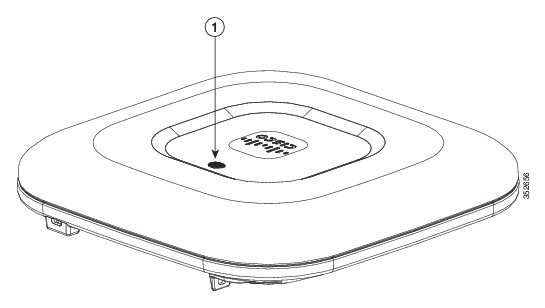
The 1702I model access point has integrated antennas and has an LED indicator on top of the unit, as shown in .
Figure 1 Access Point LED Indicator (top)—1702I Model
The ports and connections on the bottom of the access point are shown in .
Figure 2 Access Point Ports and Connections (bottom)-AIR1702I Model
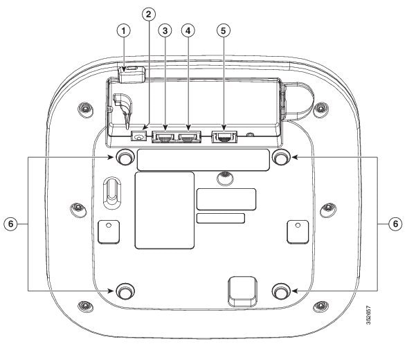
Note The Auxiliary Ethernet port is disabled. Do not connect this port to a PoE switch. Connecting the primary and auxiliary ports to a PoE switch will not provide additional power.
Configuring the Access Point
This section describes how to connect the access point to a wireless LAN controller. Because the configuration process takes place on the controller, see the Cisco Wireless LAN Controller Configuration Guide for additional information. This guide is available on Cisco.com.
The Controller Discovery Process
The access point uses standard Control and Provisioning of Wireless Access Points Protocol (CAPWAP) to communicate between the controller and other wireless access points on the network. CAPWAP is a standard, inter-operable protocol which enables an access controller to manage a collection of wireless termination points. The discovery process using CAPWAP is identical to the Lightweight Access Point Protocol (LWAPP) used with previous Cisco Aironet access points. LWAPP-enabled access points are compatible with CAPWAP, and conversion to a CAPWAP controller is seamless. Deployments can combine CAPWAP and LWAPP software on the controllers.
The functionality provided by the controller does not change except for customers who have Layer 2 deployments, which CAPWAP does not support.
In a CAPWAP environment, a wireless access point discovers a controller by using CAPWAP discovery mechanisms and then sends it a CAPWAP join request. The controller sends the access point a CAPWAP join response allowing the access point to join the controller. When the access point joins the controller, the controller manages its configuration, firmware, control transactions, and data transactions.
Note For additional information about the discovery process and CAPWAP, see the Cisco Wireless LAN Controller Software Configuration Guide. This document is available on Cisco.com.
Note CAPWAP support is provided in controller software release 5.2 or later. However, your controller must be running release 8.0.x.x or later to support 1700 series access points.
Note You cannot edit or query any access point using the controller CLI if the name of the access point contains a space.
Note Make sure that the controller is set to the current time. If the controller is set to a time that has already occurred, the access point might not join the controller because its certificate may not be valid for that time.
Access points must be discovered by a controller before they can become an active part of the network. The access point supports these controller discovery processes:
- Layer 3 CAPWAP discovery—Can occur on different subnets than the access point and uses IP addresses and UDP packets rather than MAC addresses used by Layer 2 discovery.
- Locally stored controller IP address discovery—If the access point was previously joined to a controller, the IP addresses of the primary, secondary, and tertiary controllers are stored in the access point’s non-volatile memory. This process of storing controller IP addresses on an access point for later deployment is called priming the access point. For more information about priming, see the “Performing a Pre-Installation Configuration” section.
- DHCP server discovery—This feature uses DHCP option 43 to provide controller IP addresses to the access points. Cisco switches support a DHCP server option that is typically used for this capability. For more information about DHCP option 43, see the “Configuring DHCP Option 43 and DHCP Option 60” section.
- DNS discovery—The access point can discover controllers through your domain name server (DNS). For the access point to do so, you must configure your DNS to return controller IP addresses in response to CISCO-CAPWAP-CONTROLLER.localdomain, where localdomain is the access point domain name. Configuring the CISCO-CAPWAP-CONTROLLER provides backwards compatibility in an existing customer deployment. When an access point receives an IP address and DNS information from a DHCP server, it contacts the DNS to resolve CISCO-CAPWAP-CONTROLLER.localdomain. When the DNS sends a list of controller IP addresses, the access point sends discovery requests to the controllers.
Preparing the Access Point
Before you mount and deploy your access point, we recommend that you perform a site survey (or use the site planning tool) to determine the best location to install your access point.
- Access point locations.
- Access point mounting options: below a suspended ceiling, on a flat horizontal surface, or on a desktop.
Note You can mount the access point above a suspended ceiling but you must purchase additional mounting hardware: See “Mounting the Access Point” section for additional information.
- Access point power options: power supplied by the recommended external power supply (Cisco AIR-PWR-B), a DC power supply, PoE from a network device, or a PoE power injector/hub (usually located in a wiring closet).
Note Access points mounted in a building’s environmental airspace must be powered using PoE to comply with safety regulations.
Cisco recommends that you make a site map showing access point locations so that you can record the device MAC addresses from each location and return them to the person who is planning or managing your wireless network.
Installation Summary
Installing the access point involves these operations:
- Performing a pre-installation configuration (optional)
- Mounting the access point
- Grounding the access point
- Deploying the access point on the wireless network
Performing a Pre-Installation Configuration
Note Performing a pre-installation configuration is an optional procedure. If your network controller is properly configured, you can install your access point in its final location and connect it to the network from there. See the “Deploying the Access Point on the Wireless Network” section for details.
Pre-Installation Configuration Setup
The pre-installation configuration setup is shown in .
Figure 3 Pre-Installation Configuration Setup
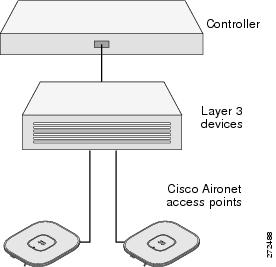
Step 1 Make sure that the Cisco wireless LAN controller DS port is connected to the network. Use the CLI, web-browser interface, or Cisco Prime Infrastructure procedures as described in the appropriate Cisco wireless LAN controller guide.
a. Make sure that access points have Layer 3 connectivity to the Cisco wireless LAN controller Management and AP-Manager Interface.
b. Configure the switch to which your access point is to attach. See the Cisco Wireless LAN Controller Configuration Guide, Release x.x for additional information.
c. Set the Cisco wireless LAN controller as the master so that new access points always join with it.
d. Make sure DHCP is enabled on the network. The access point must receive its IP address through DHCP.
Step 2 Apply power to the access point:
– Access point power injector (AIR-PWRINJ5)
– Any 802.3af compliant power injector
Note The 1702 series access point requires a gigabit Ethernet (GbE) link to prevent the Ethernet port from becoming a bottleneck for traffic because wireless traffic speeds exceed transmit speeds of a 10/100 Ethernet port.
b. As the access point attempts to connect to the controller, the LEDs cycle through a green, red, and amber sequence, which can take up to 5 minutes.
c. If the access point shuts down, check the power source.
d. After the access point finds the Cisco wireless LAN controller, it attempts to download the new operating system code if the access point code version differs from the Cisco wireless LAN controller code version. While this is happening, the Status LED blinks amber.
e. If the operating system download is successful, the access point reboots.
Step 3 Configure the access point if required. Use the controller CLI, controller GUI, or Cisco Prime Infrastructure to customize the access-point-specific 802.11ac network settings.
Step 4 If the pre-installation configuration is successful, the Status LED is green indicating normal operation. Disconnect the access point and mount it at the location at which you intend to deploy it on the wireless network.
Step 5 If your access point does not indicate normal operation, turn it off and repeat the pre-installation configuration.
Note When you are installing a Layer 3 access point on a different subnet than the Cisco wireless LAN controller, be sure that a DHCP server is reachable from the subnet on which you will be installing the access point, and that the subnet has a route back to the Cisco wireless LAN controller. Also be sure that the route back to the Cisco wireless LAN controller has destination UDP ports 5246 and 5247 open for CAPWAP communications. Ensure that the route back to the primary, secondary, and tertiary wireless LAN controller allows IP packet fragments. Finally, be sure that if address translation is used, that the access point and the Cisco wireless LAN controller have a static 1-to-1 NAT to an outside address. (Port Address Translation is not supported.)
Deploying the Access Point on the Wireless Network
Step 1 Connect and power up the access point.
Step 2 Observe the access point LED (for LED descriptions, see “Checking the Access Point LED” section).
a. When you power up the access point, it begins a power-up sequence that you can verify by observing the access point LED. If the power-up sequence is successful, the discovery and join process begins. During this process, the LED blinks sequentially green, red, and off. When the access point has joined a controller, the LED is chirping green if no clients are associated or green if one or more clients are associated.
b. If the LED is not on, the access point is most likely not receiving power.
Step 3 Reconfigure the Cisco wireless LAN controller so that it is not the Master.
Note A Master Cisco wireless LAN controller should be used only for configuring access points and not in a working network.
Troubleshooting
If you experience difficulty getting your access point installed and running, look for a solution to your problem in this guide or in additional access point documentation. These, and other documents, are available on Cisco.com.
Guidelines for Using Cisco Aironet Lightweight Access Points
Keep these guidelines in mind when you use 1702 series lightweight access points:
- The access point can only communicate with Cisco wireless LAN controllers.
- The access point does not support Wireless Domain Services (WDS) and cannot communicate with WDS devices. However, the controller provides functionality equivalent to WDS when the access point joins it.
- CAPWAP does not support Layer 2. The access point must get an IP address and discover the controller using Layer 3, DHCP, DNS, or IP subnet broadcast.
- The access point console port is enabled for monitoring and debug purposes. All configuration commands are disabled when the access point is connected to a controller.
Checking the Access Point LED
The location of the access point status LED is shown in .
Note Regarding LED status colors, it is expected that there will be small variations in color intensity and hue from unit to unit. This is within the normal range of the LED manufacturer’s specifications and is not a defect.
The access point status LED indicates various conditions and are described in .
Troubleshooting the Access Point Join Process
Note The controller must be running Cisco IOS Software Release 8.0.x.x or later to support 1700 series access points.
Access points can fail to join a controller for many reasons: a RADIUS authorization is pending; self-signed certificates are not enabled on the controller; the access point’s and controller’s regulatory domains don’t match, and so on.
Controller software enables you to configure the access points to send all CAPWAP-related errors to a syslog server. You do not need to enable any debug commands on the controller because all of the CAPWAP error messages can be viewed from the syslog server itself.
The state of the access point is not maintained on the controller until it receives a CAPWAP join request from the access point. Therefore, it can be difficult to determine why the CAPWAP discovery request from a certain access point was rejected. In order to troubleshoot such joining problems without enabling CAPWAP debug commands on the controller, the controller collects information for all access points that send a discovery message to it and maintains information for any access points that have successfully joined it.
The controller collects all join-related information for each access point that sends a CAPWAP discovery request to the controller. Collection begins with the first discovery message received from the access point and ends with the last configuration payload sent from the controller to the access point.
You can view join-related information for up to three times the maximum number of access points supported by the platform for the 2500 series controllers and the Controller Network Module within the Cisco 28/37/38xx Series Integrated Services Routers.
Note The maximum number of access points varies for the Cisco WiSM2, depending on which controller software release is being used.
When the controller is maintaining join-related information for the maximum number of access points, it does not collect information for any more access points.
- An access point running software release 8.0.x.x or later has been newly deployed.
- An existing access point running software release 8.0.x.x or later has been reset after clearing the configuration.
If any of these conditions are met and the access point has not yet joined a controller, you can also configure a DHCP server to return a syslog server IP address to the access point using option 7 on the server. The access point then starts sending all syslog messages to this IP address.
- The access point is still connected to the same controller, and the global syslog server IP address configuration on the controller has been changed using the config ap syslog host global syslog_server_IP_address command. In this case, the controller sends the new global syslog server IP address to the access point.
- The access point is still connected to the same controller, and a specific syslog server IP address has been configured for the access point on the controller using the config ap syslog host specific Cisco_AP syslog_server_IP_address command. In this case, the controller sends the new specific syslog server IP address to the access point.
- The access point is disconnected from the controller and joins another controller. In this case, the new controller sends its global syslog server IP address to the access point.
- Whenever a new syslog server IP address overrides the existing syslog server IP address, the old address is erased from persistent storage, and the new address is stored in its place. The access point also starts sending all syslog messages to the new IP address provided the access point can reach the syslog server IP address.
You can configure the syslog server for access points and view the access point join information only from the controller CLI.