
CG Triumvirate is a trademark of Agfa Corporation.
CG Times based upon Times New Roman under license from the Monotype Corporation. Windows is a registered trademark of the Microsoft Corporation.
All other brand and product names are trademarks, service marks, registered trademarks, or registered service marks of their respective companies.
Firmware (Software) Agreement
Information in this document is subject to change without notice and does not represent a commitment on the part of Datamax Barcode Products Corporation. No part of this manual may be reproduced or transmitted in any form or by any means, for any purpose other than the purchaser’s personal use, without the expressed written permission of Datamax Corporation.
Part Number: 88-2300-01

Agency Compliance and Approvals:
Information Technology Equipment
C22.2 No. 950-M93
For 230 Volt Operation (Europe): Use a cord set, marked «HAR,» consisting of a min H05VV-F cord which has a minimum 0.75 square mm diameter conductors, provided with an IEC 320 receptacle and a male plug for the country of installation rated 6A, 250V
Für 230 Volt (Europa): Benützen Sie ein Kabel, das mit «HAR» markiert ist, bestehend mindestens aus einem H05VV-F Kabel, das mindestens 0,75 Quadratmillimeter Drahtdurchmesser hat; sowie eine IEC320 Steckdose und einen für das Land geeigneten Stecker, 6A, 250 Volt.
As an Energy Star Partner, the manufacturer has determined that this product meets the Energy Star guidelines for energy efficiency.
Safety: This product complies with the requirements of EN 60950 /A11:1997
This device complies with FCC CFR 47 Part 15 Class A.
Important Safety Instructions
This printer has been carefully designed to provide many years of safe, reliable performance. As with all electrical equipment, there are a few basic precautions you should take to avoid hurting yourself or damaging the printer:
Carefully read the installation and operating instructions provided with your printer.
Place the printer on a flat, firm, solid surface.
Do not place the printer on or near a heat source.
Do not use your printer near water, or spill liquid into it.
Be certain that your power source matches the rating listed on your printer. If you are unsure, check with your dealer or with your local power company.
Do not place the power cord where it will be walked on. If the power cord becomes damaged or frayed replace it immediately.
Do not insert anything into the ventilation slots or openings on the printer.
Only qualified, trained service technicians should attempt to repair your printer.

Setting Up the Printer
Using the Front Panel

Maintenance and Adjustments
This manual provides all the information necessary to operate the printer.
To print labels or tags simply refer to the instructions included with the software you have chosen to create the labels. A Windows printer driver can be found on our website (www.datamaxcorp.com) or on the included CD-ROM. If you wish to write a custom program, a copy of the M(part number 88-2301-01) can also be found on the CD-ROM.

About this Printer
Direct Thermal Printing
On Demand and Batch Printing
203 DPI Printhead
AGFA Scalable Font Engine
Date and Time Stamp
2 MB FLASH Memory
4 MB DRAM Memory
RS-232 serial interface
IEEE 1284 Centronics parallel interface
Simple Media Loading
media compatible from the bottom and rear of printer

2 Optional Features
A printing method that uses ribbon to produce exceptional image clarity, as compared to most direct thermal media types. This option must be specified for use with either ‘coated side in’ ribbon or ‘coated side out’ ribbon.
A rotary-type mechanism to automatically cut material with a maximum thickness of .010” (.254 mm) into minimum lengths of 1.25 inches (31.8 mm).
Peel and Present Mechanism (requires the Internal Rewind option)
An output control device that automatically separates printed labels from the backing material and allows subsequent printing to occur only after the removal of a previously printed label. Minimum label length is 1.5 inches (38 mm).
An internal mechanism to wind four-inch outer diameter rolls of printed labels, or the label backing material when using the Peel and Present option.
An output control device that allows subsequent printing to occur only after the removal of a previously printed label.
External Keyboard (specify voltage / country requirement when ordering
A portable keyboard / display terminal, the DMX Passport™, for stand-alone printing.
External Ethernet Connectivity (uses printer’s parallel port)
The DMX100 External Print Server is an external Network Interface Controller (NIC) that enables the printer to provide Ethernet connectivity.
FLASH Memory Expansion (requires new main PCB)
An optional main PCB assembly is available with 4MB Flash memory expansion for International Language Printing Capability (ILPC) and/or additional fonts and graphics.
(western European) Scalable font
Kanji Gothic B Scalable font
Simplified Chinese GB Scalable font
Korean Hangul font

Before Using the Printer
Removing the Packaging
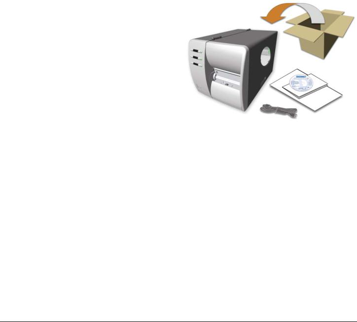
Inspect the shipping container(s) for damage; if damage is evident notify the shipping company to report the nature and extent of the damage.
Ensure that the arrow on the box is pointing up, and then open the box.
Remove the top piece of packing foam.
Lift the printer from the box.
Remove the printer from the plastic bag.
Remove any tape or additional packing foam from the inside of the printer.
It is a good idea to save all packaging materials in the event that shipping the printer is ever required.
Inspecting the Printer
Any special or additionally purchased items.
Serial, USB or Parallel cable
This chapter explains how to connect your printer, load media (and ribbon, if equipped for thermal transfer), and print a configuration label.
1 Connecting the Printer
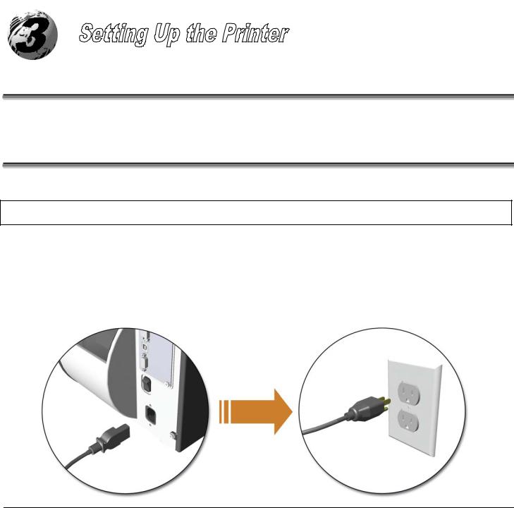
When connecting the AC Power Cord or interface cables to the printer, ensure the Power On/Off Switch is in the ‘Off’ position.
Place the printer on a firm, level surface.
Ensure that the Power Switch on the Printer is in the ‘Off’ position.
Connect the AC Power Cord to the receptacle on the back of the Printer, and then plug the AC Power Cord into a properly grounded outlet. (The power supply automatically detects and then adjusts to the applied line voltage; see Section 7.0 for the acceptable voltage ranges.)
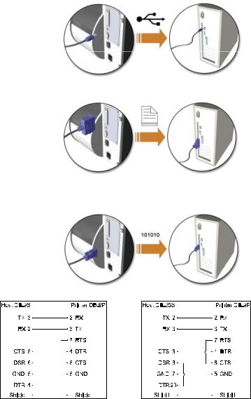
2 Interface Connection
The printer can be connected to the host via a USB, serial or parallel cable. The Printer will automatically connect to the first port (USB, serial or parallel) that transmits valid data. After this connection has been made, the printer’s power must be cycled ‘Off’ and ‘On’ to change the interface connection.
The USB Interface is supported in Windows 95 and greater. Depending upon the operating system of your host computer, installation may differ slightly.
The parallel interface requires a Centronics IEEE 1284 cable with a 36 pin male connector. Bi-directional mode is IEEE 1284 Compliant, using forward and reverse channel communications. In this mode, data can be sent to the host provided it is also IEEE 1284 Compliant and has supporting software.
Baud Rate (Default 9600 bps)
Word Length (Default 8 bits)
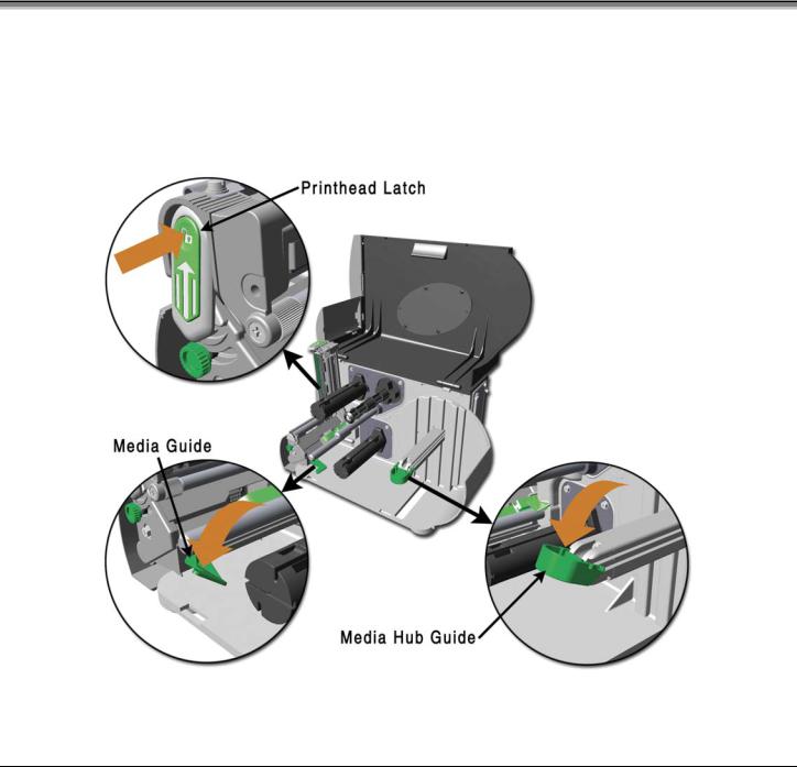
1. Open the media cover and lower the Media Hub Guide and Media Guide. 2. Press in on the Printhead Latch and raise the Printhead Assembly.
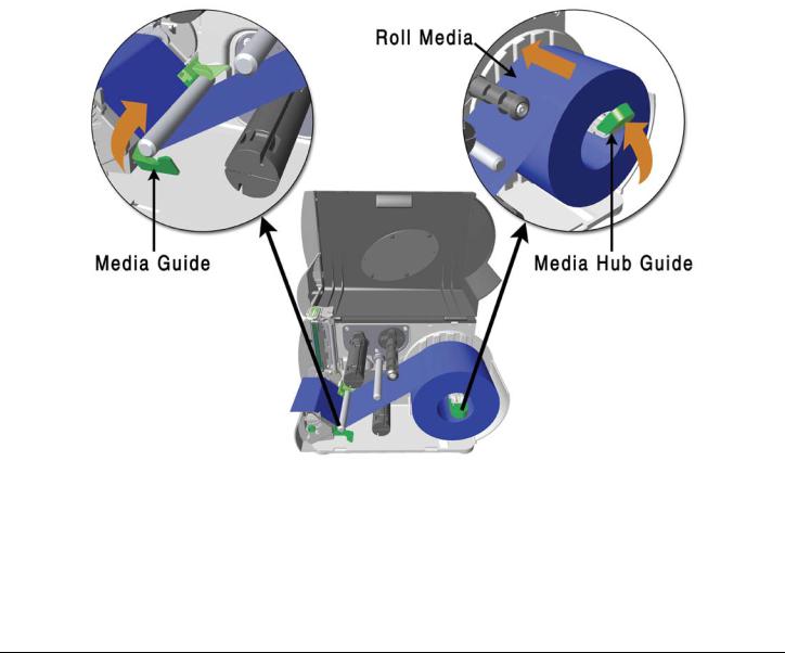
3. Slide the Roll Media onto the Media Hub and raise the Media Hub Guide. The Media Hub Guide should be pushed inward so that it is just touching the Roll Media.
4. Route the Media through the printer as shown. Raise the Media Guide. The Media Guide should be pushed inward so that it is just touching the edge of the Media.
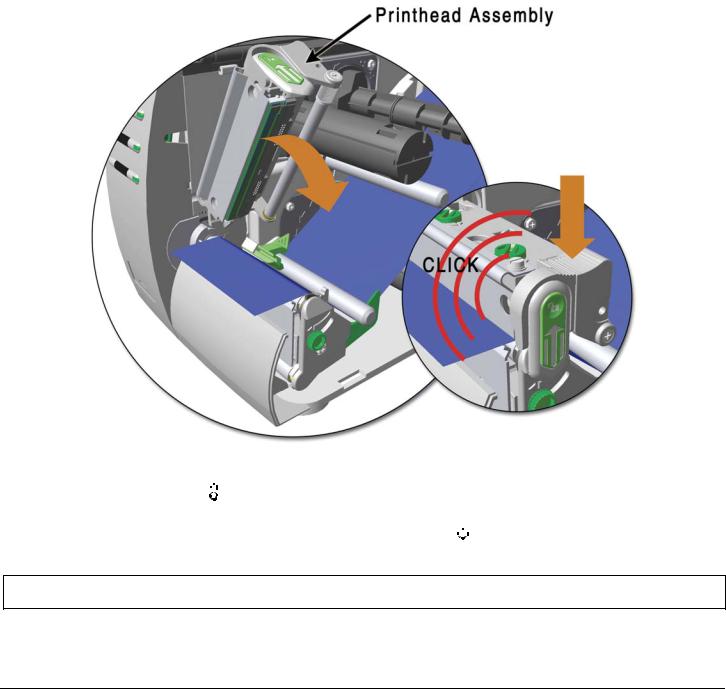
5. Close the Printhead Assembly and press down until it locks into place.
6. Close the cover and press the


If the printer does not correctly sense the top of each label, as denoted by the


light, it may be necessary to perform the Calibration Procedure, see section 4.7.1.
The printer is factory set to use 4-inch media (and ribbon, if thermal transfer equipped). When using a different width of media/ribbon, please refer to section 5.2.
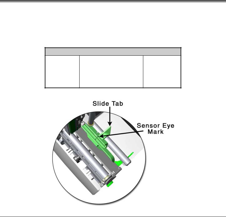
Media Sensor Adjustment
The Media Sensor needs to be positioned so that the printer can detect the presence of media and the top-of-form (except for continuous stock, where the TOF is set through the front panel, (see CONT FORM LENGTH’, Section 4.5.2). To adjust:
With media loaded, as described in Section 3.2, grasp the Slide Tab and move the Sensor Eye Mark into position over media according to the table below.
If loading media, return to the media loading instructions.
Media Sensor Selection and Adjustment
See Section 4.5.2 for Sensor Type selection.
4 Loading Ribbon
Ribbon is required with thermal transfer media. It is recommended that the width of the ribbon be slightly wider than the media being used. Depending upon the type of Ribbon Supply Hub (see 3.4.1 for examples), the printer must use either ribbons with the ‘coating side in’ ribbons with the ‘coating side out’. To load:
Using a ribbon that is slightly wider than your media (and liner, if any) will help protect against printhead wear.
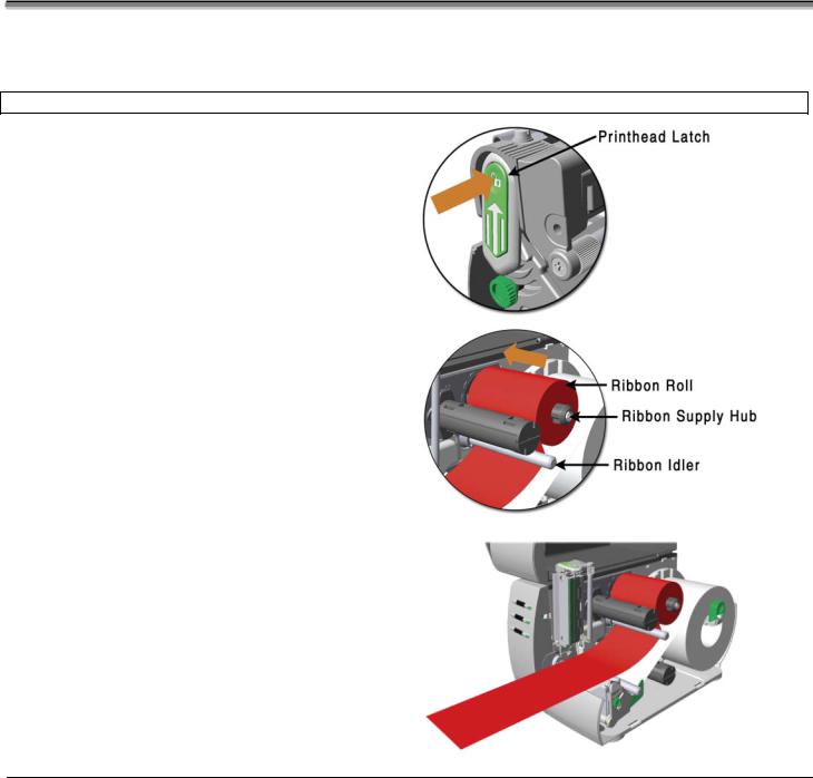
Open the media cover. Press in on the Printhead Latch and raise the printhead assembly.
Slide the Ribbon Roll onto the Ribbon Supply Hub until it rests against the hub’s flange. Ensure the ribbon unwinds in the correct direction (see 3.4.1 for examples). Illustrations depict a ‘Coated Side In’ assembly.
Route the ribbon under the Ribbon Idler and then out the front of the printer approximately 12 inches.
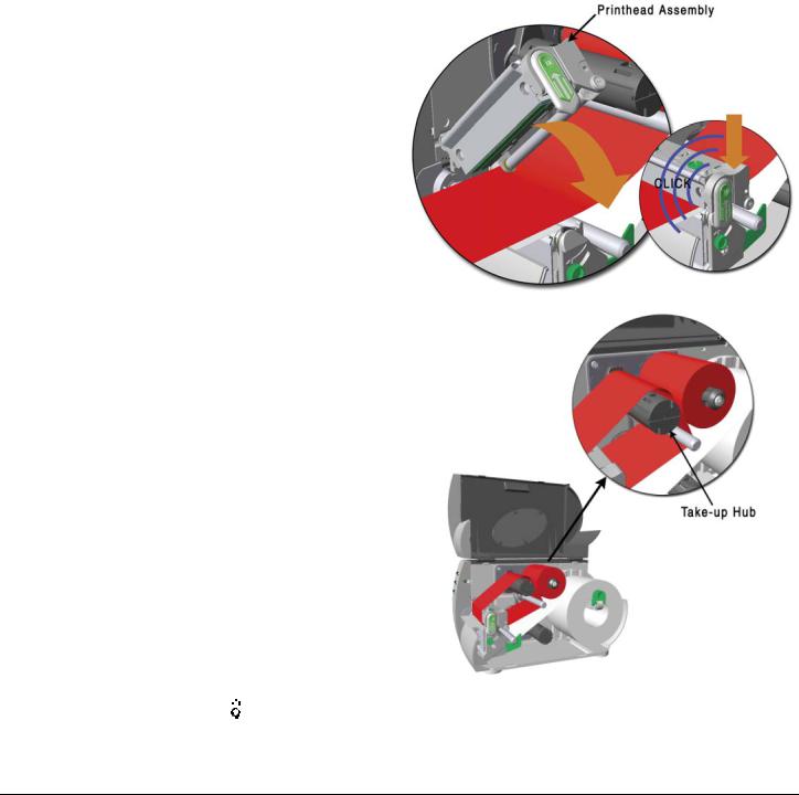
Route the ribbon up and then around to the Ribbon Take-Up Hub, winding it several times in a clockwise direction to secure it in place.


button several times to position the ribbon and ensure proper tracking.
7. The ‘Media Type’ setting within the printer’s setup must be set to ‘Thermal Transfer’ to print using a ribbon, see section 4.5.2.
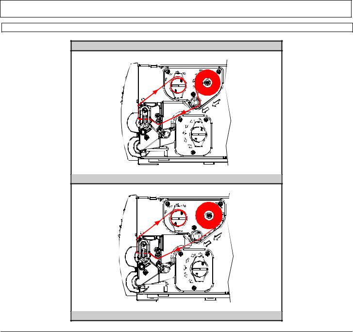
3.4.1 Ribbon Routing (Coated Side In & Coated Side Out)
Directional Arrows near the Ribbon Supply Hub indicate the correct ribbon route. Ribbon types are available with the ink (coating) layer wound ‘in’ or ‘out’. These types are NOT interchangeable for use with the printer.
Ensure the inked side of the ribbon faces the media and the printhead.
Ribbon Routing Diagrams
‘Coating Side In’ Ribbon Supply Hub
‘Coating Side Out’ Ribbon Supply Hub
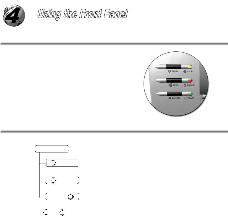


Allows quick access to the most common printer settings, (Sensor Type, Media Type, and Option Control. See Section 4.4.
Allows changes to the printer’s operational settings. See Section 4.5.
Allows the ‘calibration’ of the media being used for the correct sensing of the top of form. See Section 4.7.
Normal Mode — Button Functions
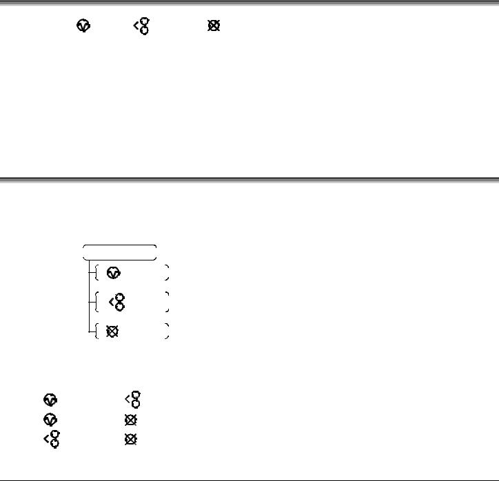
In ‘Normal’ mode, the printer’s buttons control normal operations such as pause, feed, and cancel, as well as the test and reset functions by using button combinations as detailed below.
(push buttons simultaneously)